MP Pumps FRX75-SP 316 Stainless Self Priming Centrifugal Pumps 3/4" NPT
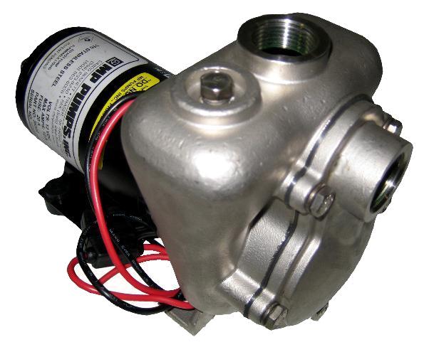
Model FRX 75-SP is a high performance self-priming 316 stainless steel centrifugal pump. The pump is ideal for marine, industrial, agricultural or commercial applications where suction lift is required.
The FRX 75-SP model features all 316 stainless steel components for superior corrosion resistance when pumping chemical compounds. A carbon/ceramic/viton bellows shaft seal is standard. Ports are 3/4" NPT with 1/8" NPT fill port. The O-ring/flapper design enhances the self-priming capability to 12 foot suction lift. Marine ignition protected motors available.
Resources


Questions & Answers
- What is cavitation?
- The increase velocity of the water entering a pump will cause a reduction in pressure within a unit. If this pressure falls too low, some of the water will vaporize, forming bubbles entrained in the liquid. These bubbles collapse violently as they move to areas of higher pressure creating the noise and vibration from the pump.
- How do you know if the pump is cavitating?
- The pump is cavitating if knocking noises and vibrations (like pumping gravel) can be heard when it is operating. Other signs may be erratic power consumption and fluctuations or reductions in pump output.
- Will a centrifugal pump work if it is running backwards?
- A centrifugal pump accelerates water off the tips of the impeller vanes. When an impeller is running backward, the centrifugal forces will still accelerate the water - although far less efficiently. A backward running pump will deliver less water, at a lower pressure, and will typically consume less electricity. If the impeller is threaded to the shaft, it may unscrew when running backwards.
- My pump starts and stops a lot. Will this hurt the motor?
- Yes it will.... If you start the motor too many times, a buildup of heat can cause damage to the motor. Every time the motor starts, the inrush current of up to 10 times the nameplate amps (locked rotor code M). The motor dissipates the inrush of energy as heat.
- What does water hammer sound like?
- It sounds like somebody is hitting the pipe with a sledge hammer.
- If I put a bigger motor on my pump, will it pump more?
- No. The amount of water and the pressure (head) that a centrifugal pump produces is related to the rotational speed, impeller diameter and size of the impeller vanes.
-
What is the relationship between flow low and pressure?
- When the flow increases, the discharge pressure of the pump decreases, and when the flow decreases the discharge pressure increases
- Can a pump be run at zero flow for an extended period of time?
- Do not let a centrifugal pump operate for long periods of time at zero flow. The friction of the impeller will make water will boil, the mechanical seal will "burn", all plastic componenets will melt and water will possibly leak into the motor windings In residential systems, the pressure switch shuts the pump down when the pressure is high which means there is low or no flow.
- What is a centrifugal pumps minimum flow rate?
- There is no standard which establishes precise limits for minimum flow in pumps. Most centrifugal pumps should not be used at a flow rate less than 50% of the best efficiency point. If the system requires a flow rate of 50% or less then use a recirculation line to increase the flow through the pump keeping the flow low in the system. If a pump operates at at very low flows, it could overheat badly and cause noise, vibration, cavitation and mechanical damage.
- Should a install pressure gauges in the system?
- Make sure your pump has a pressure gauge on the discharge side close to the outlet of the pump this will help you diagnose pump system problems. It is also useful to have a pressure/ vacuum gauge on the suction side; the difference in pressure is proportional to the total head. The pressure gauge reading will have to be corrected for elevation since the reference plane for total head calculation is the suction flange of the pump.
- Can a centrifugal pump run dry?
- Make sure that the pump is always full of liquid; most centrifugal pumps cannot run dry. In residential systems, to make sure that the pump stays full of the liquid use a check valve in line or a foot valve at the end of the suction line. Use of check valves to isolate pumps installed in parallel.
- What kind of isolation valves should I use?
- Gate valves or full flow ball valves should be used as these offer no resistance to flow and can provide a tight shut-off. Butterfly valves are often used but they do provide some resistance and their presence in the flow stream can potentially be a source of hang-ups which would be critical at the suction. Butterfly valves close faster than gate valves but are not as leak proof.
- What kind of reducer should I use on the suction side?
- Always use an eccentric reducer at the pump suction when a pipe size transition is required. Put the flat on top when the fluid is coming from below or straight and the flat on the bottom when the fluid is coming from the top. This will avoid an air pocket at the pump suction and allow air to be evacuated.
- Where do I install the isolation valve to control the pump flow?
- If you need to control the flow, use a valve on the discharge side of the pump; never use a valve on the suction side for this purpose.
- Why is there air in my system?
- Avoid pockets or high point where air can accumulate in the piping. An ideal pipe run is one where the piping gradually slopes to the suction of the pump and up from the pump discharge. This will ensure that any air in the the pump can be evacuated.
- What is Water hammer?
- Water hammer or hydraulic shock is a pressure surge resulting when water in motion is forced to stop or change direction suddenly. Water hammer commonly happens when a valve is closed suddenly at an end of a pipeline system, and a pressure wave if formed in the pipe. This pressure wave can cause major problems, from noise and vibration to pipe collapse. It is possible to reduce the effects of the water hammer pulses with accumulators and other features. For pumps 500 GPM or larger use valves at the discharge that is controlled to open gradually when starting the pump. This will avoid water hammer during the initial start and damage to the piping system.
- What pipe size should I use?
- The right pipe size is a compromise between cost and excessive friction loss that will affect the pump performance. As a rule of thumb the discharge pipe size should not be smaller than the pump discharge connection. For the suction side, you can also use the same size pipe as the pump suction connection and increase it by one pipe size for every 50 feet of suction pipe. A typical velocity range used for sizing pipes on the discharge side of the pump is 8-12 ft/s and for the suction side 3-6 ft/s. The actual pipe sizes should be determined by calculating the friction loss of the whole system.
- What happens when centrifugal pumps are run in parallel?
- When two or more pumps are arranged in parallel their resulting performance curve is obtained by adding their individual capacities at the same head. Centrifugal pumps in parallel are used to deliver larger flows than one pump can handle alone. Parallel operation adds pump capacity while the head stays the same.
- What happens when centrifugal pumps are run in series?
- When two or more centrifugal pumps are arranged in series their resulting pump performance curve is obtained by adding their heads at the same flow rate (capacity). Centrifugal pumps in series are used to deliver more system head than one pump can handle alone. Series operation adds pump head while the capacity stays the same.
- What happens if you do not have enough submergence?
- The end of the suction pipe is not submerged deeply enough, a vortex will form at the surface and cause air to be entrained in the pump reducing the pump capacity.
- What centrifugal pump do I need?
- A centrifugal pump should be selected based on total head and flow requirements. Pump selection starts with getting detail information about the system. If you are just replacing an existing pump with an exact replacement, then there is no problem. If you are replacing an existing pump with problems or looking for a pump for a new application then we respectfully suggest that you contact a qualified and competent specifying engineer.
- Will air in pump reduce its capacity?
- When air enters a pump it sometimes gets trapped in the volute, this reduces the capacity, creates vibration and noise. To remedy, shut the pump down and open top casing plug vent and remove the air. If the pump is excessively noisy do not automatically assume that the problem is cavitation, air in the pump creates vibration and noise.
- What is the effect of viscosity on pump performance?
- Viscosity is the main criteria which determine whether the application requires a centrifugal pump or a positive displacement pump. Centrifugal pumps can pump viscous fluids however the performance is adversely affected. If your fluid is over 2000 SSU in viscosity consider using a positive displacement pump.
- What is the shut off head in a centrifugal pump?
- The shut-off head, this is the maximum head that the pump can achieve and occurs at zero flow. The pump will be noisy and vibrate excessively at this point. The pump will consume the least amount of power at this point. Do not let a centrifugal pump operate for long periods of time at zero flow. The friction of the impeller will make water will boil, the mechanical seal will "burn", all plastic components will melt and water will possibly leak into the motor windings In residential systems, the pressure switch shuts the pump down when the pressure is high which means there is low or no flow.
- What is the Best Efficiency Point (BEP)?
- The best efficiency point B.E.P. this is the point at which the pump is the most efficient and operates with the least vibration and noise. This is often the point for which pumps are rated and which is indicated on the nameplate. The pump will consume the power corresponding to its B.E.P. rating at this point.
- What is the maximum flow point?
- It is the point, on the right side of the curve, past which the pump may not operated. The pump will be noisy and vibrate excessively at this point. The pump will consume the maximum amount of power at this point.
- What are the three different types of pump curves?
- They are normal curves, flat curves and drooping curves. In a normal curve the head decreases rapidly as flow increases. Ina flat curve the head decreases very slowly as flow increases. The drooping curve is similar to the normal curve except that the head raises then drops as it gets near to the shut-off head point.
- Are there any advantages to using a pump with a drooping curve?
- The drooping curve shape is to be avoided because it is possible for the pump to hunt between two operating points which both satisfy the head requirement of the system. This is known to happen when two pumps are in parallel, when the second pump is started it may fail to get to the operating point or hunt between two points that are at equal head. Thankfully not to many pumps have this characteristic.
- When is a flat curve desirable?
- A flat curve is sometimes desirable since a change in flow only causes a small change in head as in a sprinkler systems. As more sprinklers are turned on the head will tend to decrease but because the curve is flat the head will decrease only a small amount which means that the pressure at the sprinkler will drop only a small amount, thereby keeping the water velocity high at the sprinkler outlet.
- Are normal curves steep?
- The normal curve can be more or less steep. A steep curve can be desirable from a control point of view since a small change in flow will result in a large pressure drop. The steepness of the curve depends on the number of vanes and the specific speed.